Last Updated: 05/07/01 10:18 PM
Week 7 Review Questions (answers at end of page):
A. You don't know on which layer a red line on your screen resides. How do you find out? B. You dimension an object in Paper Space and the number displayed is MUCH smaller than the size at which you drew the object. What do you do to fix it? C. You want to freeze a layer of an XREF but you don't know the name of the layer. What can you do? D. You insert a object such as an Xref or Block but when you are done with the insert command, your screen looks the same. What are two possible problems and what do you do to fix them? E. The drawing you were given does not have the correct dimension style. What is the easiest way to make the current drawings style match your "standard".
Plotting and Pen Weights:
Print Command:
- Review Plotting, Pen Assignments, Scaling and Device Defaults.
- Create simple pen assignment chart and save to file.
- Review relationship of plotted line weight to object color and layer.
- Review On-line Help.
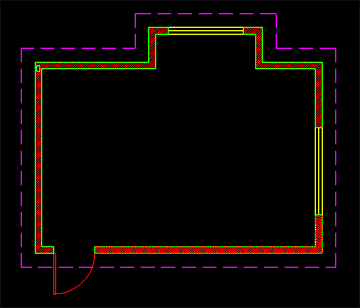
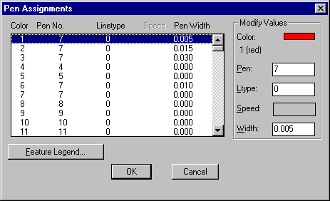
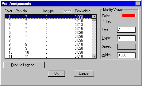
The following example attempts to show the results of plotting a simple floor plan with a specific pen assignment table: This file...

...printed with this pen assignment table...

yields these results:

![]()
Review Question Answers:
A. You don't know on which layer a red line on your screen resides. How do you find out?
- Click on it. When you select an object by clicking on it, the layer of that object appears on the Object Properties toolbar.
- List the object's properties: Use either the LIST command (inquiry toolbar) or Properties button on Object Properties toolbar. Either one will tell you more than you want to know about the funny red line.
B. You dimension an object in Paper Space and the number displayed is MUCH smaller than the size at which you drew the object. What do you do to fix it?
- Set DIMLFAC variable: Set the variable DIMLFAC (type it at the command prompt), which probably stands for dimension linear factor, to the scale of the viewport which contains your object. If the scale of your viewport is 1/10" = 1'-0", that's the same as 10' per inch (inverse). Since Architectural units are in inches, you must convert by multiplying feet x12, or 10x12=120. Set DIMLFAC to 120.
- Change the Dimension Style: You can also click through dialog boxes and change the linear dimension scaling factor. Click the dimension style button on the dimensioning toolbar, or type DDIM at the command prompt, click Annotation, then Units and set the linear scale to the scale of the viewport from which you want to dimension. See 1 above.
C. You want to freeze a layer of an XREF but you don't know the name of the layer. What can you do?
- Use the Bonus toolbar's Freeze by Entity button. Click the button, then click the object. You may be prompted whether you want just the entity or the entire Xref. You choose.
D. You insert a object such as an Xref or Block but when you are done with the insert command, your screen looks the same. What are two possible problems and what do you do to fix them?
- Zoom Extents: Usually this happens because the screen was zoomed way in when you inserted a large object. Because you may have selected a point on the screen as the insertion point, the newly inserted object may be much bigger than the amount of space the screen is looking at. By zooming to the extents of the drawing, you should see everything visible.
E. The drawing you were given does not have the correct dimension style. What is the easiest way to make the current drawings style match your "standard".
- Dimstyle Import: Go to Menu>Bonus>Tools>Dimstyle Import... Browse your way to the file that contains the dimension style you prefer (use Dimstyle export to create it...). If you have "extensions" turned on in Windows 95 or 98 then you are looking for a file with an extension of ".dim".
![]()
Reading: Frey, Skill 14


