Drawing from Xrefs & Plotting![]()
Last Updated: 05/07/01 09:25 PM
Week 6Review Questions (answers at end of page):
A. How would you create a new text style and change current drawing text to that style? B. If you receive a drawing from a colleague or consultant that is drawn in decimal feet and you wish to convert it to architectural units, what would you do? C. If a linetype (dashed, for example) appears too small, that is the dashes are too small and close together, what can you do to fix it? D. You insert a detail bubble block with attributes (text) and forget to enter the values at the time of insertion. Now you want to go back and add the text. How do you do that? E. You have drawn both roof and floor plan information in a single model. In Paper Space you created two viewports. Both show all the model layers and are not displayed to scale. What should you do to create a 1/4" floor plan and a 1/8" roof plan?
More on Dimensioning:
Reusing Dimension Styles in other drawings: Clearly, creating dimension styles is a lot of work. You do not, however have to recreate the style each time you start a new drawing. Instead you can save the style to disk and import it into another drawing.
- To write the style to a file: Menu>Bonus>Tools>Export.... Several similarly named files may exist. For example Style1, Style1$0, Style$1, etc. Select all of the files with similar names (i.e. all the Style1's in this example). Give it a file name and save it somewhere that makes sense (...YourName folder\Dimension Styles\Style1.dim)
- To import a previously saved dimension style, go to Menu>Bonus>Tools>Import..., find the file you want, and click Open. The saved style will load into your current drawing.
Drawing from Xrefs:
Xref, Clipping:
- XCLIP command: (from AutoCAD On-line Help...) After attaching a drawing as an xref or inserting a block, you can define a clipping boundary by using XCLIP. A clipping boundary can define a portion of a block or xref while suppressing the display of geometry outside of the boundary. Clipping applies to an individual instance of an xref, not the xref definition itself. The portion of the xref or block within the clipped boundary remains visible, and the remainder of the xref or block becomes invisible. The referenced geometry is not altered, only the display of the xref is edited.
You can use XCLIP to create a new clipping boundary, delete an existing boundary, or generate a polyline object coincident with vertices of the clipping boundary. Xref clipping can be turned on or off. When a clipping boundary is turned off, the boundary is not displayed and the entire xref is visible, provided that the geometry is on a layer that is on and thawed. When a clipping boundary is turned off, it still exists and can be turned on. However, deleting a clipping boundary is permanent. For more information about XCLIP, see the Command Reference.
After an xref or block has been clipped, it can be edited, moved, or copied just like an unclipped xref or block. The boundary moves with the reference. If an xref contains nested clipped xrefs, they appear clipped in the drawing. If the parent xref is clipped, the nested xrefs are also clipped.
XCLIP is used on external references and blocks to set both a clipping boundary and a front or back clipping plane. A clipping boundary consists of planar straight line segments.- Reference toolbar: XCLIP or Command line: xclip
Select objects: Use an object selection method and press ENTER when you finish selecting objects
Enter clipping option [ON/OFF/Clipdepth/Delete/generate Polyline/New boundary] <New>: Select an option or press ENTER. Review options.
Plotting and Pen Weights:
Plot Command:
- Review Plotting, Pen Assignments, Scaling and Device Defaults.
- Create simple pen assignment chart and save to file.
- Review relationship of plotted lineweights to object color and layer.
- Review On-line Help.
![]()
Review Question Answers:
A. How would you create a new text style and change current drawing text to that style?
- Create the Style: Use Menu>Format>Text Style... In the dialog box that appears click New. Give your new style a name (may be helpful if Style name is close or matches actual font name). Click ok. In the Font Name pull down window select the font you wish to assign to the new style. A preview of the font should appear in the lower right corner. Once you like it, click apply, then Close.
- Change the Properties: Next, click either Menu>Modify>Properties... or the Properties button on the Object Properties toolbar and select the text you wish to change. A Modify text (or Mtext) dialog box pops up. In this dialog box change the Style from its current setting to the one you just created. You're done.
B. If you receive a drawing from a colleague or consultant that is drawn in decimal feet and you wish to convert it to architectural units, what would you do?
- Change the Units: Use Menu>Format>Units... and select Architectural. While you're in the dialog box you might also consider checking the precision to make sure it's what you want.
- Scale the drawing: Since Architectural units are ALWAYS IN INCHES you need to scale the entire drawing by the number of architectural units in each decimal foot, or by 12. First make sure all layers are THAWED. Frozen layers will not be modified. Use the Scale button on the Modify toolbar (or use menu...), when prompted to select objects, type all or drag a window around everything. Hit return to stop selecting things and then type 12 followed by return. You're done.
C. If a linetype (dashed, for example) appears too small, that is, the dashes are too small and close together, what can you do to fix it?
- Change the Objects Linetype Scale: Using the Properties command (Menu>Modify>Properties...) change linetype to a larger number. Remember that if you have the system set up to use paper space units for scaling (Layer and Linetype Properties>Linetype tab>Details...) then objects whose linetype seems small in MODEL space, my view correctly in PAPER space. You'd have to toggle into Paper Space (doubl-click TILE on Status Bar) and view the object through a viewport. I know, it's stupid.
- Change the global linetype scaling variable: Use Menu>Format>Linetype... press Details... and change the global scale factor. Or type LTSCALE at the command prompt and enter the value you want. If you were to print from Model Space, you would set the LTSCALE to the plotscale. For example, if you were going to plot a quick 1/4" scale view of your floor plan and didn't want to set up a layout in paper space, you could set LTSCALE to 48 (1 plotted unit to 48 drawing units--remember to convert to inches) and your object's linetypes would scale correctly.
D. You insert a detail bubble block with attributes (text) and forget to enter the values at the time of insertion. Now you want to go back and add the text. How do you do that?
- Modify Attribute: Either use Menu>Modify>Object> Attribute>Single... or the Edit Attribute button on the Modify II toolbar, or type DDATTE and the command line. Click the block whose text you want to change. In the dialog box that appears, enter the appropriate changes, then click O.K.
E. You have drawn both roof and floor plan information in a single model. In Paper Space you created two viewports. Both show all the model layers and are not displayed to scale. What should you do to create a 1/4" floor plan and a 1/8" roof plan?
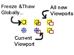
- Freeze and Thaw layers to correctly display the information: In the veiwport to be the floor plan, freeze all roof plan information. To do this, either click Menu>Format>Layer or click in the pull-down window on the Object Properties toolbar. Find all layers with the word "roof" in them and freeze them IN THE CURRENT VIEWPORT which is different from freezing them globally, or in future new viewports.
Next, switch to your other viewport and do the same for the floor plan layers. Do not freeze layer "0" or layer "Defpoints" since doing that may cause your Paper Space viewports to disappear.
- Scale the viewports: Either use the zoom command or MVSETUP. To use the ZOOM command, first drop into floating model space by double-clicking on the PAPER button on the status bar. Next choose Menu>View>Zoom...>Scale or type ZOOM at the command window. Now enter the scale factor-- it is a relationship between Model Space units and Paper Space units. To show the floor plan at 1/4" = 1'-0" the relationship is 1 Paper Space unit to 4x12 Model Space units (remember everything must be converted to inches) or 48. Therefore type 1/48xp. The "xp" tells the computer the relationship involves paper space. If you want to use MVSETUP, type the command at the command prompt, choose the option of "S" for Scale Viewports, select the viewport you want to scale, and enter the same relationship described above. For the Roof Plan you would enter 1 for the first entry and 96 (8x12) at the second. Remember to get back into Paper Space after you scale a viewport to avoid accidentally panning or zooming in Floating Model Space.
![]()
Reading: Frey, Skill 8&10