![]()
Last Updated: 05/21/01 11:09 PM
Week 8Creating 3-D Geometry (Much of this week's notes are taken from AutoCAD's help files):
See BasicCAD Review, Week 8
| Last week we
dove into simple 3D solid modeling. Solids are easy to
manipulate and therefore useful to designers. However, there
are really THREE different ways to create 3D geometry. This
week we'll review another useful method of created complex
geometry: SURFACE models.
|
|
Creating Complex GeometryAlthough 3D models can be more difficult and time-consuming to create than 3D views of 2D objects, 3D modeling has several advantages. You can
AutoCAD supports three types of 3D modeling:
wireframe, surface, and solid. Each type has its own creation and editing techniques. |
|
 |
A WIREFRAME model is a skeletal description of a 3D object. There are no surfaces in a wireframe model; it consists only of points, lines, and curves that describe the edges of the object. Because each object that makes up a wireframe model must be independently drawn and positioned, this type of modeling can be the most time-consuming. |
 |
SURFACE modeling is more sophisticated than wireframe modeling in that it defines not only the edges of a 3D object, but also its surfaces. The AutoCAD surface modeler defines faceted surfaces using a polygonal mesh. Because the faces of the mesh are planar, the mesh can only approximate curved surfaces. AutoCAD calls faceted surfaces, meshes. |
 |
SOLID modeling is the easiest type of 3D modeling to use. With the AutoCAD solid modeler, you can make 3D objects by creating basic 3D shapes: boxes, cones, cylinders, spheres, wedges, and tori (donuts). You can then combine these shapes to create more complex solids by joining or subtracting them or finding their intersecting (overlapping) volume. You can also create solids by sweeping a 2D object along a path or revolving it about an axis. |
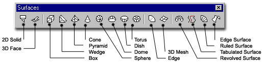
NOTE: Because each modeling type uses a different method for constructing 3D models and editing methods vary in their effect on the different model types, it is recommended that you not mix modeling methods. Limited conversion between model types is available from solids to surfaces and from surfaces to wireframes; however, you cannot convert from wireframes to surfaces or from surfaces to solids. Surface Tools: |
|
|
|
|
|
2D Solid creates a solid filled polygon. Point pick order affects layout. SOLID 3DFace Creates a three-dimensional face. Point pick order affects layout. 3DFACE Cone, Pyramid, Wedge and Box create surface objects like their names suggest Sphere makes a spherical surface mesh. Dome makes the top half of a sphere, Dish the bottom half. Tours makes a surface ring like a doughnut or car tire. Edge changes the visibility of surface edges. |
|
 |
3DMESH
AutoCAD defines a polygon mesh by a matrix, the size of which is determined by M and N size values. M � N equals the number of vertices that you must specify. Specify location for vertex (0, 0): Enter a 2D or 3D coordinate AutoCAD defines the location of each vertex in the mesh by m and n, the row and column indices of the vertex. Defining vertices begins with vertex (0,0). You must supply the coordinate locations for each vertex in row m before specifying vertices in row m + 1. Vertices may be any distance from each other. The M and N orientation of a mesh depends on the position of its vertices. 3DMESH polygon meshes are always open in both M and N directions. You can close a mesh with PEDIT. |
 |
|
| RULED
SURFACE Command line: rulesurf Select first defining curve: Select second defining curve: The objects you select define the edges of the ruled surface. The objects can be points, lines, splines, circles, arcs, or polylines. If one of the boundaries is closed, then the other boundary must also be closed. You can use a point as the other boundary for either an open or a closed curve, but only one of the boundary curves can be a point. The 0,0 vertex is the endpoint of each curve nearest the point you used to select that curve. For closed curves, the selection does not matter. If the curve is a circle, the ruled surface begins at the 0-degree quadrant point, as determined by the current X axis plus the current value of the SNAPANG system variable. For closed polylines, the ruled surface starts at the last vertex and proceeds backward along the segments of the polyline. Creating a ruled surface between a circle and a closed polyline can be confusing. Substituting a closed semicircular polyline for the circle might be preferable.  The ruled surface is constructed as a 2 � N polygon mesh. RULESURF places half the mesh vertices at equal intervals along one defining curve, and the other half at equal intervals along the other curve. The number of intervals is specified by the SURFTAB1 system variable. It is the same for each curve; therefore, the distance between the vertices along the two curves differs if the curves are of different lengths.
|
|
| Tabulated
Surfaces
Surfaces Toolbar: Command line: TABSURF |
|
| Revolved Surface (Revsurf) works much like the solid modeling tool, REVOLVE but create a mesh instead of a 3D solid. | |
|
The system variable SURFTAB1 controls the mesh density in the m direction of the new mesh. SURFTAB2 controls the mesh density in the n direction. Both must be integers between 2 and 256. Greater mesh density makes surfaces look smoother, but quickly increases file size and may result in poor computer performance. Be careful to create meshes only as dense as they need to be.
|
|
Creating 3D Landforms: |
|||
 |
Using a
survey of a landform, you can create a simple 3D model.
First, make sure your contours are polylines or spline curves. Use
the PEDIT command to JOIN line segments if necessary. Next,
ensure that they are at the correct elevation in 3D space.
For example, contour 435' should have a constant Z value of
435. If you have a flat (two-dimensional) survey, you must
first "move" all contours to their correct
elevations. The CHANGE command can quickly accomplish this
task. Better yet, make a new button (see week
5 ) and use the following script to add a level of automation
to the task: ^C^C_change;p;e;\;
|
||
 |
If you want to check
your work, create a 3D View (3D Dynamic View, Camera). The
image at left is a perspective view from the NW. You can see
that the slop of the land is from a high point at the NE down to
the NW corner.
Next, set the SURFTAB1 and SURFTAB2 variables to control the mesh density. The larger the number, the denser the mesh and the larger the file size. When using the Ruled Surface command shown next, the computer will divide each contour into SURFTAB1 equal sections. See below. |
||
 |
 |
 |
Change to the layer you want to use
for the surfaces. Start the Ruled Surface |
|
The result is something like the image
at left. Shade your view to better evaluate the results
(Regenerate the view to return to wireframe).
Note that each rise in elevation equals one different ruled surface. To combine all surfaces into one object, use the 3DSOUT command to export all desired surfaces to a file (select all surfaces to be combined). Use 3DSIN command to import the glued-together mesh. |
||
| The resulting mesh can be used to make site models. Add bodies of water by using 3DFACE or creating a 3D solid at the right elevation. Great for underlays for hand sketched work. | |||
![]()
Assignment: Exercise 4, due at beginning of class, Week 9