Creating a 2D layout from a 3D model
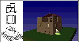
1. Find views in View menu > Edit Cone of Vision. Adjust with View Parameters and Save Views.
2. Measure the model to find the correct image size. Measure a verifiable part of the model, then estimate the overal image size in model scale (here the building walls are centered 8 meters apart, so the overal image would be 12 meters).
3. Set the rendering size through the Display menu > Image options dialogue box. For example, to have this image print out well at 12" wide on a 300 dpi printer, it should be 1200 pixels wide. The resulting image would have approximately 1" = 1 meter.
4a. Render the component views. While FormZ wire frame images can be copied from 3D Modeling to 2D draft, the Imager is needed to make editable Hidden Line drawings. From the File menu, choose New Imager Set, then Add the name of the file and select the View and Rendering Type desired.
4b. To create a FormZ file from the hidden-line process, go into the Imager Setup.
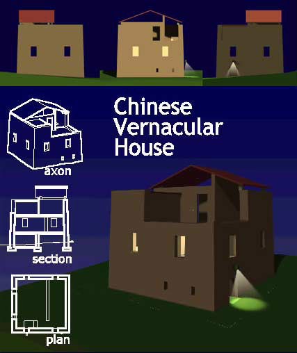
5. Layout the component views in FormZ draft. Open each hidden-line file generated by the imager, copy and paste the components onto the same Draft window. In the windows menu, you can turn off the grid and the axis lines.
Add text, adjust line colors, lineweights and line types. Print, Save to JPG format, setting Image size in Display > Image Options.
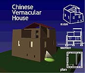
6. Try rearranging and adding components to create a more effective panel.
edited 11/21/00 by nywcheng