Let's say I have a drawing of the site shown in the photo above that looks something like this. Working from this graphical information, one could approximate the site conditions in AutoCAD as follows:
Exercise 1 – Drawing a Site Plan
LA 408/508 Intermediate CAD Workshop * Spring 2001 * Barwood
Last Updated: 04/10/01 12:38 PM
Due at the beginning of class on April 17, 2001 in class folder:
"Courses on Andromeda" K:\LA408-CADworkshop\Submitted Exercises\Exercise1\Ex1-YourInitials.dwg
|
Goal: Develop skills in drawing a site plan with CAD software. Develop good layer management skills.
|
Background: We will be developing a simple community park in the next four exercises. The site, program, and detail of this park is up to you. My intention is to use the design process as a vehicle to explore the use of computers for drawing. The design, while always important to people in our professions, is secondary to the CAD work in this class. There are many ways of generating site plan information electronically. The easiest, for landscape architects, is to import an electronic survey, generated by a professional land surveyor. It is also possible to "trace" over a picture or "raster image" of the site. Both methods will be explored later in the class. For this exercise, generate the information yourself, making the best approximation you can.
|
Assignment: Draw an electronic site plan using AutoCAD. Choose a site with which you are familiar and for which you have access to paper drawings. It should be relatively small--perhaps between 2 and 10 acres. The actual size is up to you. The site should be based on reality, but you may take liberties with the geography as needed to satisfy these exercises--the point being not to spend too much time trying to find "the perfect site". Instead, practice setting up a new drawing, create appropriately named layers, draw the land features, insert blocks, etc. Use color to distinguish between layers. DO NOT PRINT THE DRAWING. Instead, submit the electronic version to the location shown above. Include the following annotations in your model: contour information, property line information For example: |
|
|
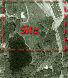
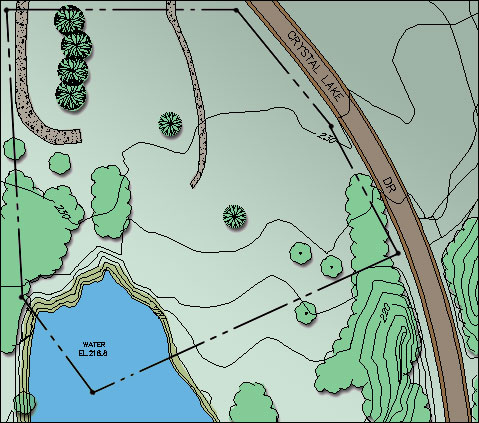
For the purposes of this example, I have chosen a site in Corvallis. The image at left attempts to show the area used for the example. In the drawing below I've graphically represented the site as a paper drawing might depict. Obviously, I've embellished reality for the sake of simplicity. |
Let's say I have a drawing of the site shown in the photo above that looks something like this. Working from this graphical information, one could approximate the site conditions in AutoCAD as follows:
|
|
|
|
|
A couple of suggestions: