H.W. Lefevre, M.S. Chmelik, R.J. Rasmussen, R.M.S. Schofield,
G.E. Sieger, and J.C. Overley
Department of Physics, University of Oregon, Eugene, Oregon, USA
The University of Oregon scanner now uses 16 neutron time-of-flight spectrometers to produce an image of the elemental composition of each 3x3 cm2 pixel in a bag by stepping the bag through a fan beam. We now spend 80 seconds of counting time on each slice so that a 60 cm long bag scanned in 20 steps requires 27 minutes. In order to speed the process for airport use, several individual changes are required. First, the accelerator current must be increased 20-fold to increase neutron flux. Such an accelerator is available now. Second, electronic deadtime must be reduced 20-fold to accomodate the increased counting rate. Work on this is proceeding. Third, ten rows of 16 detectors will allow a 60-cm long bag to be scanned in two steps. When these three factors are combined, one obtains a counting time of 8 seconds. This paper describes our present spectrometer system and it outlines a practical system for use at an airport.
In 1984 Overley(1) demonstrated a technique for quantitative analysis of H, C, N, and O in bulk samples by de-convoluting the measured attenuation of a fast-neutron spectrum using elemental cross-sections. The contribution from other elements was lumped together as fictitious element X with an energy independant cross-section. In 1995, Overley et al. (2) described application of the technique to detection of plastic explosives hidden in airline luggage. In 1996 Lefevre et al(3) and Overley et al.(4) reported on the use of a 16 detector neutron time-of-flight (TOF) spectrometer to study real explosives in real luggage.
Since then blind tests involving 140 pieces of luggage and eight types of explosives have been carried out. The results of those tests and the algorythms used for explosives detection are described in another paper at this conference (5). This paper describes our present system, and outlines a path toward a practical system for first-line use at an airport.
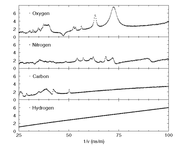
Figure 1 shows the cross-sections of H, C, N, and O plotted as a function of normalized flight time, or 1/v nanoseconds per meter (ns/m). Since spectroscopy is by time-of-flight, data are kept in the time domain. For reference, 1/v values of 25, 50, and 100 ns/m correspond closely to energies of 8, 2, and 0.5 MeV. Where cross-sections are large the neutron spectrum is strongly attenuated. The elements imprint their cross-section signatures upon the transmitted spectrum in accord with the amount of each element present. A computer program does a least squares fit of the cross-sections to the attenuation to obtain quantities of the elements present.
Figure 1.
Figure 2 shows the geometry of our TOF spectrometer system. A continuous spectrum of neutrons with energies up to 8.2 MeV is produced by a nanosecond pulsed beam of deuterons stopping in a beryllium metal target. The spectrum from the locally shielded target is collimated to a horizontal fan shaped beam and is delivered to a row of 16 6 cm square plastic scintillators located 4 m from the target. Luggage is stepped through the fan beam in 3 cm steps by an automated lift halfway between the target and the scintillators. The scintillators are coupled to 12 stage photomultiplier tubes, constant fraction discriminators, time-to-amplitude converters (TACs), analog-to-digital converters (ADCs) and histogramming memories. A computer controls the system asynchronously through a CAMAC crate. It also reads the memories, controls the lift, and analyzes the data.

Figure 2.
Figure 3 shows the TOF spectrometer logic diagram. The 16 spectrometers are individually calibrated by enabling the time mark generator for 5 seconds, and reading and analysing the time-mark data. Live charge for each spectrometer must be recorded in each neutron spectrum since losses depend upon rates and rates depend upon the luggage. The circuitry shown allows beam-current integrator pulses to be stored at a selected place in every TOF spectrum.

Figure 3.
Figure 4 shows normalized TOF spectra from a measurement with a 6-cm thick sample of Semtex H explosive. A log scale is used for the ordinate to span the 4 decade range in counts per 0.2 ns/m per 100 uC of deuterons. The prompt gamma peak is at the left while the charge peak is placed at the right. The background was recorded by raising the detector array out of the fan beam.

Figure 4.
Before scanning luggage, unattenuated spectra and background spectra are recorded. Transmission spectra are then recorded one slice at a time and transferred to the computer while the location of the lift is advanced by one pixel width (3 cm). As the next set of spectra is collected, the computer calculates attenuations for the earlier slice, deconvolutes the attenuations into projected number densities, and determines the explosive likelyhood (b-value) for each pixel through a look-up table that is addressed according to coordinates determined by the number densities. When a scan is completed, spatially correlated pixels are examined to determine an explosive likelyhood for the whole suitcase, and it can be tested against an alarm threshold. The techniques used to generate the explosive likelyhood table for each pixel, and for a whole suitcase are described in a companion paper (5).
In addition to measuring the attenuation of the neutron spectrum, the attenuation of prompt gamma rays from 9Be(d,n,g) and 9Be(d,p,g) reactions is also measured. The gamma ray attenuation is primarily due to Compton scattering. It is proportional to the projected electron density of the attenuator, and that is proportional to the product of projected atomic number density with the (number) average atomic number, of the pixel. We form the ratio of gamma ray attenuation (ga) with the neutron attenuation (na) averaged over several channels at the high energy end of the neutron spectrum (8 to 5.5 MeV). The ratio is almost independant of sample thickness and it increases with . Figure 5 shows the ratio ga/na for several elemental attenuators, for several non-explosive compounds, and for several explosives. Table 1 contains ga/na for the data of Figure 5.
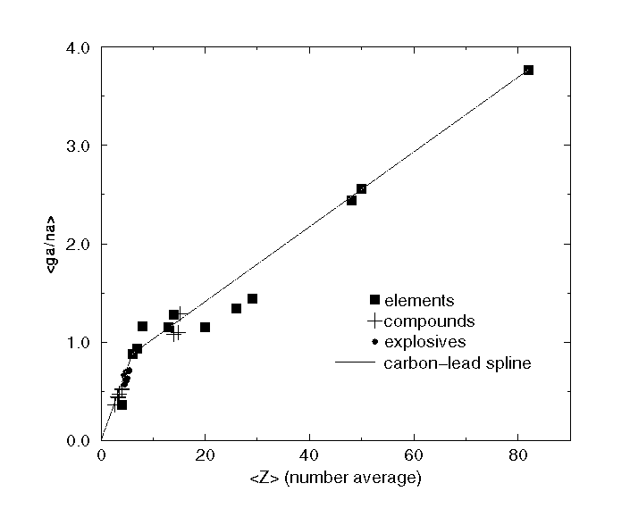
Figure 5.
Figure 6 shows two gray-scale maps obtained from one suitcase from our blind tests. The first shows explosive likelyhood (b-values) where black is inocuous and white is explosive. Partly filled pixels are marked with circles and should be ignored. A sheet of explosive is indicated in the lower left corner. The second grey-scale map contains Z values. The large white rectangular area has Z values up to 40. It was identified as lead by including the lead cross-section in the deconvolution. The pixels marked with circles indicate poorer than usual fits (higher values of chi-squared) to the attenuation. When the data was reprocessed including the lead cross-section the fits dramatically improved. The b-values were originally innocuous but after reprocessing with lead added, the positive explosive indication shown in Figure 6 appeared.

Figure 6a.

Figure 6b.
Installation of this technique at an airport will be a major undertaking. It may be time to plan for it in the design of new concourses. We will outline a possible layout as we see it now. It appears to us that if false alarm and missed explosives rates are deemed to be acceptably low, the technique can be made fast enough for routine use.
Our present scanning requires 1600 seconds of counting time to scan a 20 pixel (60 cm) long bag at 80 seconds per slice. With 10 rows of detectors the bag could be scanned with two positions in 160 seconds. The deuteron beam current can be increased from our present 1 uA to 20 uA with a commercially available accelerator. So the combination of those two steps will yield a counting time of 8 seconds. Luggage transport and positioning will require additional time as well.
          ELEMENTS               COMPOUNDS                EXPLOSIVES

             Z  ga/na                Z     ga/na                Z      ga/na

         Be  4  0.357      HDPE     2.67   0.358    C4        5.04    0.630
         C   6  0.881      H2O      3.33   0.435    ANFO      4.50    0.567
         N   7  0.931      Nylon    3.26   0.441    SemtexH   4.84    0.609
         O   8  1.159      TrisBase 3.47   0.475    NGdyna    4.75    0.698
         Al 13  1.150      Urea     4.00   0.512    TNT       5.43    0.718
         Si 14  1.281      Sucrose  4.04   0.521    TNTboost  5.39    0.708
         Ca 20  1.154      NaCl     14.0   1.083    Watergel  4.30    0.662
         FE 26  1.343      CCl4     14.8   1.099    DetaSheet 4.73    0.614
         Cu 29  1.437      Fe2O3    15.2   1.285
         Cd 48  2.437
         Sn 50  2.558
         Pb 82  3.770
NOTES:  For compounds, Z was calculated from the chemical formula.
        For explosives, Z was calculated from our elemental deconvolution
        of measured attenuations. The ratios of  gamma ray attenuation (ga)
        to neutron attenuation (na) were   measured. The neutron attenuation
        was an average over the  interval from 25 to 35 ns/m.
An increase of a factor of 20 in counting rate will require some changes in our spectrometers. Since this is a spectroscopic technique one is faced with all of the questions that arise in quantitative spectroscopy. When one speeds measurements by 20-fold, one must re-examine dead times, backgrounds, dynamic range, spectrum distortions, data handling and analysis. None of the questions that we can forsee appear to be intractible.
We will use time-to-digital converters (TDCs) to decrease the dead time of our present TAC-ADC system. TDCs with acceptable differential nonlinearity and a clock rate of 4 Ghz appear to be achievable using recent Motorolla chips as we have established with a prototype. It hasen't yet been tested it with neutrons. It will only accept one neutron per beam pulse per detector so spectra will have to be corrected for the distortion caused by event shadowing. Event shadowing occurs when only the first neutron from a beam pulse is analysed and subsequent events are lost. The correction will be approximately 10 fold larger but it can be analytically made.
An increase of counting rate by a factor of 20 will also require that photomultiplier gain be reduced by about that amount by reducing high voltage. And that will require a different technique for biasing the constant fraction discriminators. The neutron spectrum itself can be used for setting biasses since the shape of the spectrum at long flight times is sensitive to the bias setting.
Figure 7 is a drawing of an accelerator system that National Electrostatics Corp. of Middleton, Wisconsin has proposed for this use. It uses a Torvis high current negative ion source with harmonic chopping and bunching to deliver a 20 uA average current of bunched 4.2 MeV deuterons (6). It has a quoted spark rate of 2 or less per day, and a quoted up-time of 95% including scheduled maintainence. The deuteron beam can be quickly intercepted in a Farady cup before acceleration and the voltage of the terminal will remain at 2.1 MV. The beam can be transported an focused to a diameter of 5 mm or less on a Be target. A Cooling system will have to be devised to accomodate 80 watts of disappated beam power.

Figure 7.
Figure 7 also shows a transport system that uses a 90 degree magnet and a pair of quadrupole triplet lenses to produce a vertically directed neutron beam. The target and colimator are 1 m below floor level. The luggage conveyor is 1 m above the floor, and the neutron detectors are 2 m above that. This geometry nicely allows the accelerator to be in a ground level vault. Luggage is handled at concourse level, and the neutron detectors are well off the floor in otherwise unused space. A labrynth would still be needed around the scanning location to shield people from scattered radiation and that has not yet been designed.